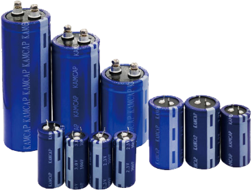




A supercapacitor charging circuit must limit initial inrush current, prevent the capacitor or bank from exceeding its rated voltage, control heat during the low-voltage stage, and keep series-connected cells balanced. A small backup capacitor may need only a resistor, reverse-current blocking device, and regulated supply. A large or fast-charged bank normally needs a constant-current/constant-voltage charger, thermal protection, and cell balancing. A supercapacitor charging circuit is an electronic power stage that transfers energy into a supercapacitor at a controlled current and voltage while protecting the source, capacitor, and load. Because a discharged supercapacitor can be close to 0 V, connecting it directly to a low-impedance supply may create damaging inrush current.
For an ideal capacitor:
I = C × dV/dt
The approximate constant-current charge time is therefore:
t = C × (Vfinal − Vinitial) / Icharge
Charging a 100 F supercapacitor from 0.5 V to 2.5 V at 2 A takes about 100 seconds in the ideal constant-current region. Understanding the mechanism of supercapacitor energy storage helps explain why terminal voltage rises in proportion to charging current and time. Actual charging takes longer when the charger reduces current at low voltage, enters thermal regulation, powers a parallel load, or tapers current near the target voltage.
Texas Instruments describes the usual charging profile as constant-current charging followed by constant-voltage regulation in its application note, How to Quickly and Safely Charge Supercapacitors. At the beginning of the cycle, thermal regulation may reduce the available charging current because the charger must handle high power loss while the capacitor voltage is still low.
When charging supercapacitors from a fixed power rail, designers must consider both current and voltage. A simple super capacitor charging circuit based on a resistor behaves differently from a regulated charger. Its initial current is approximately:
Iinitial = (Vsupply − Vcap) / Rlimit
Current is highest when the supercapacitor is empty and falls as voltage rises. This is economical for low-current backup circuits, but it wastes energy and makes recharge time less predictable.
Current limiting protects the source, connector, PCB traces, switching devices, and capacitor. The design should be evaluated at the lowest expected capacitor voltage, when circuit stress is usually highest.
Common circuit options include:
Series resistor: Suitable for small capacitance and non-critical recharge time. Check the resistor’s pulse energy and continuous power rating.
Linear current-limited charger: Compact and electrically quiet, but best when input voltage exceeds charge voltage and current is modest. Early-cycle heat can be high because power loss is roughly (Vin − Vcap) × Icharge.
Buck charger: Efficient when the input voltage is higher than the required capacitor voltage. It is useful for higher charge current and shorter recharge time.
Buck-boost charger: Appropriate when input voltage may be above or below the capacitor-bank voltage.
eFuse or current-limited switch: Useful for controlling inrush current in backup-power circuits that do not need a dedicated charger IC.
The correct super capacitor charger is not simply the device with the highest current rating. It must match the available source power, target voltage, capacitance, required recharge time, and cooling conditions. Texas Instruments’ comparison places linear charging solutions at lower currents, while switch-mode chargers are more suitable as capacitance and required charging current increase.
Set the regulated charging voltage below the supercapacitor’s maximum continuous rating after considering component tolerance, supply variation, voltage ripple, and operating temperature. For a series-connected bank, regulating only the total bank voltage is not sufficient. Individual cell voltages must also remain within their specified limits.
Voltage can divide unevenly because individual cells differ in capacitance, leakage current, and ESR. Two balancing methods are commonly used:
Passive balancing: A resistor is connected across each cell. This method is simple and inexpensive, but continuously consumes power.
Active balancing: Comparators, shunt devices, MOSFETs, or dedicated balancing ICs redirect charge away from higher-voltage cells. This approach is better suited to larger banks and systems requiring low standby loss.
Analog Devices describes an active balancing method that prioritizes charging of the lower-voltage cell and maintains the two cell voltages within a controlled window, even when the cells have mismatched capacitance. Reverse-current blocking should also be included so that stored energy does not flow back into an unpowered source. A diode is simple but introduces a forward-voltage drop. An ideal-diode MOSFET arrangement reduces this loss.
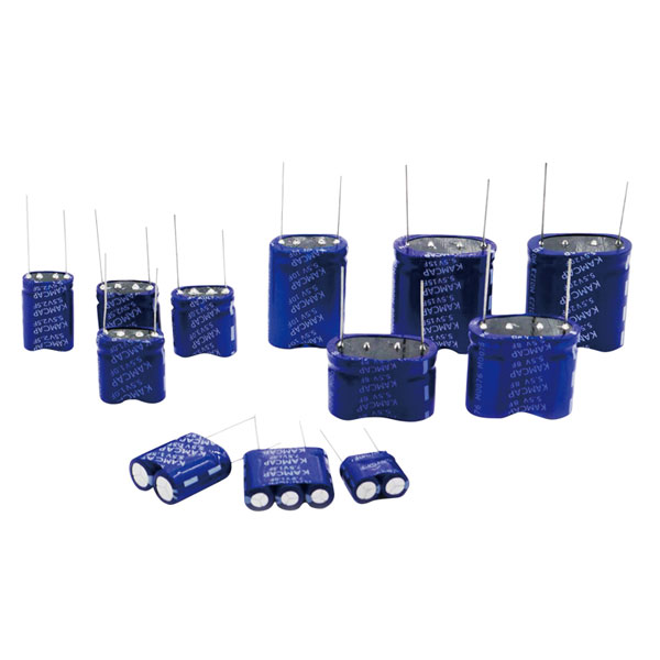
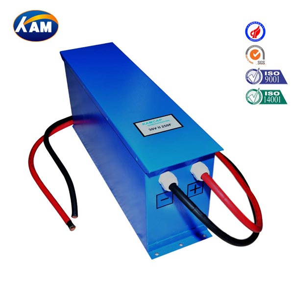
A controlled discharge path is advisable where technicians may access the equipment. Designers should also confirm polarity before assembly because many supercapacitors are polarized. For higher-voltage applications, a pre-engineered supercap module may reduce cell-integration work. Kamcap’s MK module supercapacitors combine series and parallel cell arrangements with a protection circuit for industrial backup, vehicle starting, medical equipment, and power-distribution terminal applications.
A charge discharge curve supercapacitor plot can reveal charger current, ESR effects, leakage, balancing behavior, thermal limiting, and load sharing. During constant-current charging, capacitor voltage should rise almost linearly. An immediate voltage step at the beginning of charging is mainly related to ESR:
ΔVESR = I × ESR
After this initial step, the voltage slope is approximately I/C. When the capacitor approaches its regulation voltage, the charger enters constant-voltage mode and charging current decreases.
During discharge, the same effects appear in reverse. An immediate ESR-related voltage drop is followed by a gradual voltage decline determined by load current and capacitance.
The following measurements are particularly useful during circuit validation:
Initial inrush current and peak input power
Time spent in thermal regulation
Voltage difference between series-connected cells
Final voltage at minimum and maximum input conditions
Capacitor temperature during repeated charging cycles
Standby leakage of the complete circuit
Voltage drop across protection and reverse-blocking components
For engineers asking how to charge a supercapacitor fast, increasing the current limit is only part of the answer. Fast charging also requires sufficient source power, an efficient converter, low-resistance PCB traces and cables, suitable thermal design, and a low esr supercapacitor selected for the required pulse current.
| Application | Suggested Kamcap Product | Charging Circuit Approach | Main Design Checks |
|---|---|---|---|
| RTC, memory, and smart-meter backup | 5.5V coin type supercapacitors | Regulated rail with resistor or low-current limiter | Leakage, backup time, PCB orientation, reverse current |
| Embedded backup and moderate pulse loads | 2.7V winding type supercapacitors | Linear charger, buck charger, or eFuse current limiting | Capacitance, ESR, peak current, temperature rise |
| Higher power with fewer series cells | 3V winding type supercapacitors | CC/CV switch-mode charger | Charge-voltage tolerance, current limit, cooling |
| Higher-voltage industrial energy bank | MK module supercapacitors | Module-compatible charger with system monitoring | Module voltage, cabling, protection coordination, discharge safety |
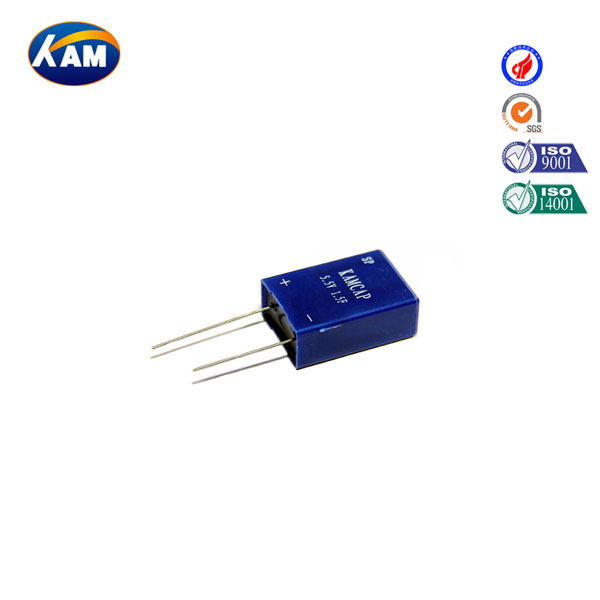
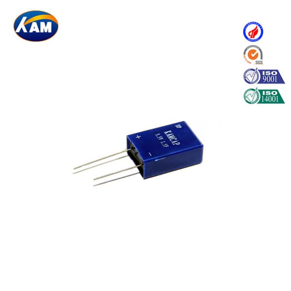
Kamcap lists a capacitance range of 0.1–3000 F for its 2.7 V winding series, 1–500 F for its 3 V winding series, and 0.1–1.5 F for its 5.5 V coin series. These options cover applications ranging from low-current memory backup to high-current energy buffering.
Before approving a supercap charger circuit, test it under maximum input voltage, minimum capacitor voltage, highest expected ambient temperature, and maximum intended capacitance. Validation should also include:
Shorted-output behavior
Charger restart after a fault
Repeated charge and discharge cycling
Source brownout and recovery
Transition from normal supply to backup power
Individual cell voltage under long-term float charging
Component temperatures inside the final enclosure
IEC 62391-1:2022: Fixed Electric Double-Layer Capacitors for Use in Electric and Electronic Equipment provides standard terminology, inspection procedures, and test methods for fixed electric double-layer capacitors used in DC electronic equipment. It can therefore serve as a useful starting point when preparing a component qualification plan. Kamcap can support capacitance, rated voltage, ESR, dimensions, installation format, and application matching for OEM projects. The final charging profile should always be confirmed against the selected product datasheet and tested with production-representative samples.
Only when the power supply has an appropriate current limit and cannot exceed the capacitor’s rated voltage. Otherwise, a nearly empty capacitor may draw excessive inrush current and overload the supply or PCB.
Small backup capacitors may use a resistor and regulated rail. Larger or fast-charge systems benefit from CC/CV control because it provides predictable current, accurate final voltage, and better thermal management.
For an approximate constant-current calculation, use:
t = C × ΔV / I
Additional time should be allowed for thermal limiting, conversion losses, parallel load current, and the constant-voltage stage.
Individual cells have different capacitance and leakage characteristics. Without balancing, one cell can exceed its rated voltage even when the total bank voltage appears correct.
Sometimes, but battery-specific pre-charge, termination, and recharge logic may be unsuitable. Use a charger with configurable settings or follow a validated supercapacitor reference design.
Increase charging current only after checking source capacity, converter efficiency, component temperature, capacitor ESR, wiring resistance, and individual cell voltages under worst-case conditions.
Kamcap specializes in the development, production, and sales of supercapacitors. If you are interested, please contact us by phone +86-18640666860 or email info@kamcap.com.


 English