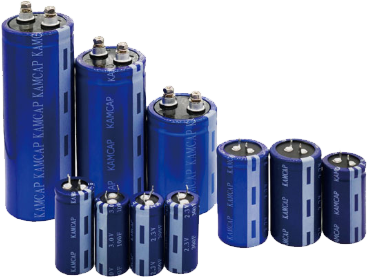




A supercaps UPS can provide short-duration backup or ride-through power when the primary supply is interrupted. In industrial automation, communication equipment, control systems, and other critical electronics, supercapacitors are especially useful when the system requires rapid energy delivery and frequent charge-discharge operation.
Designing a reliable supercap UPS, however, requires more than selecting a high-capacitance component. Engineers must evaluate load power, required backup time, usable voltage range, equivalent series resistance (ESR), peak current, charging conditions, and the architecture of the complete energy-storage system.
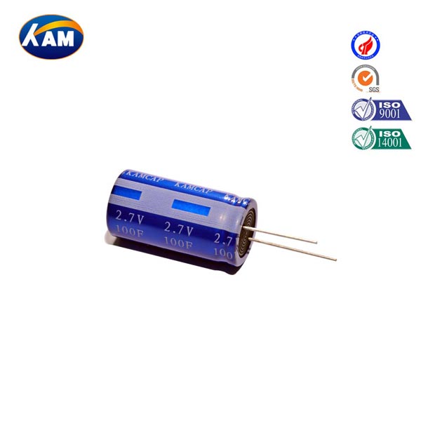
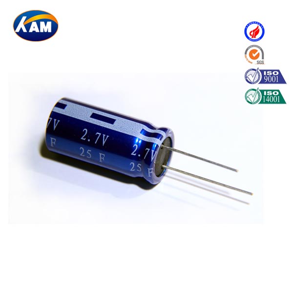
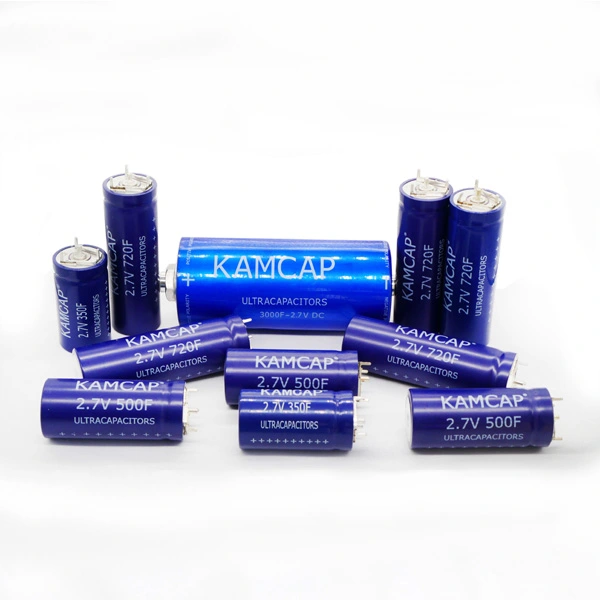
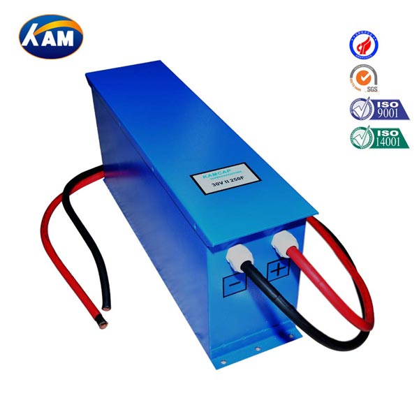
KAMCAP provides supercapacitor cells and modules for industrial backup-power applications, allowing engineers to select configurations according to electrical, mechanical, and operating requirements.
Before calculating capacitance, engineers should define exactly what the backup system needs to accomplish. Some systems only need to bridge a brief power interruption. Others must keep controllers or communication equipment operating long enough to save data, perform a controlled shutdown, or transfer to another power source.
The main design inputs include:
Continuous load power and transient peak current
Required ride-through or backup duration
Nominal and minimum acceptable bus voltage
Expected charge-discharge frequency
Operating temperature and environmental conditions
Available installation space and charging capability
The U.S. Department of Energy-supported Grid-Scale Energy Storage Technologies Primer includes supercapacitors among electrical energy-storage technologies and compares their operating characteristics with other storage options. This broader energy-storage context is useful when determining whether a supercapacitor architecture fits a high-power, short-duration application.
A clear load profile prevents both undersizing and unnecessary oversizing of the UPS energy-storage bank.
For an approximately constant-power load, the required backup energy can initially be estimated as:
E = P × t
where E is energy in joules, P is load power in watts, and t is backup duration in seconds.
The stored energy of a capacitor is based on capacitance and voltage. NASA technical documentation gives the standard capacitor energy relationship as E = ½CV². For a bank discharging between maximum voltage V₁ and minimum voltage V₂, usable energy can therefore be expressed as:
E = ½C(V₁² − V₂²)
This gives an initial capacitance estimate:
C = 2Pt / (V₁² − V₂²)
The equation explains why voltage window matters in an ups supercapacitor design. Allowing a wider voltage decrease makes more stored energy available, while a narrow acceptable voltage range may require greater capacitance or an appropriate DC/DC conversion stage.
The calculated capacitance should not automatically become the final specification. Converter efficiency, capacitance tolerance, temperature, ESR losses, aging, and engineering reserve should also be considered.
Capacitance indicates available energy, but supercap ESR affects how effectively that energy can be delivered. When a high current is drawn from the capacitor bank, internal resistance produces an immediate voltage drop and dissipates power as heat.
Engineers should therefore evaluate:
ESR under expected operating conditions
Continuous and peak discharge current
Initial voltage drop during backup transition
Resistance from cells, connections, and busbars
Thermal effects during repeated operation
NASA's detailed ultracapacitor technology assessment explains that ESR represents the capacitor's internal resistance and relates capacitor power capability directly to voltage and ESR. It also notes the general distinction between capacitors' high power capability and batteries' higher energy-storage capability.
For UPS engineering, this means a bank can have sufficient theoretical energy yet still experience excessive voltage drop if its resistance is too high. Energy capacity and instantaneous power capability should therefore be validated together.
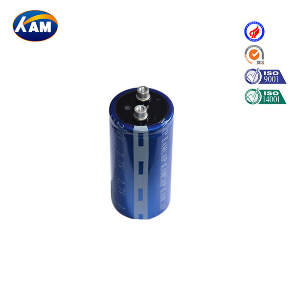
A supercapacitor bank can be assembled from discrete cells or implemented with integrated supercapacitor modules. Discrete cells provide greater flexibility when engineers need a customized series-parallel configuration. However, the complete system must address cell balancing, mechanical assembly, connections, insulation, monitoring, and protection.
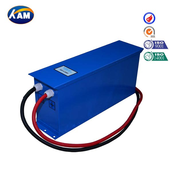
A module integrates multiple cells into a more defined system-level assembly, potentially reducing part of the mechanical and electrical integration work.
| Design Factor | Discrete Cells | MK Module |
| Configuration flexibility | High | Defined by module design |
| Mechanical integration | Requires more design work | More integrated |
| Voltage scaling | Requires series configuration | Based on module rating |
| Installation complexity | More assembly required | Can simplify integration |
| Typical fit | Customized designs | System-level applications |
KAMCAP's MK module approach can be considered when the project requires a more integrated energy-storage unit, while discrete cells may be suitable when engineers need greater freedom over voltage, capacitance, packaging, or mechanical configuration.
The final choice should reflect the complete UPS architecture rather than component cost alone.
A detailed specification sheet allows a supercapacitor supplier to evaluate the actual application instead of recommending components based only on nominal capacitance.
The document should state continuous load power, peak current, required backup duration, nominal voltage, minimum acceptable voltage, charging voltage, recharge-time target, operating temperature, available installation dimensions, and expected cycling frequency. It should also identify whether the UPS uses a direct DC connection, DC/DC converter, or inverter.
For higher-voltage systems, series connection and voltage management also need attention. Cell-to-cell differences can cause voltage imbalance, making appropriate balancing and monitoring important parts of the complete design.
The U.S. Department of Energy's Electrical Energy Storage research report provides a detailed technical discussion of electrochemical capacitors, including ESR and the physical factors contributing to internal resistance. This is useful background when specifying high-power capacitor systems rather than considering capacitance as the only electrical parameter.
Providing complete electrical, environmental, and mechanical requirements helps KAMCAP evaluate an appropriate cell or module configuration more efficiently.
Designing a reliable supercaps UPS requires coordinated evaluation of stored energy and power delivery. Capacitance, backup duration, voltage range, ESR, peak current, temperature, charging strategy, and system architecture all influence real-world performance. Engineers should begin with the required load energy, then validate voltage drop, current capability, operating conditions, and appropriate design margins. Choosing between discrete cells and an MK module should likewise be based on the complete UPS requirement rather than capacitance alone. For KAMCAP supercapacitor selection, module configuration, or project support, contact +86-18640666860 or info@kamcap.com.
Backup time depends on load power, usable capacitance, voltage range, ESR, conversion efficiency, and the operating limits of the system.
It can be suitable for certain short-duration backup requirements. Longer-duration applications may require a different storage technology or a hybrid architecture.
Recharge time depends on capacitance, voltage change, available charging current, charger capability, and thermal limitations.
Series connection increases the working voltage of the capacitor bank when system voltage exceeds the rated voltage of an individual cell.
Individual cells in a series stack may not share voltage equally, so balancing helps maintain each cell within its intended operating range.
Useful information includes load power, peak current, backup time, voltage range, charging conditions, operating temperature, installation space, and expected cycling requirements.

 English