



A super capacitor bank is built by connecting supercapacitor cells in series to raise operating voltage and in parallel to increase capacitance, stored energy, and current capability. A super capacitor bank is an energy-storage assembly made from multiple supercapacitor cells, interconnects, balancing components, and protection devices that operate as one electrical unit. It may also be called an ultra capacitor bank or supercapacitor battery bank.
Connecting identical supercapacitors in series increases voltage capability but reduces equivalent capacitance. For Ns identical cells:
Bank voltage: Vbank = Ns × Vcell
Equivalent capacitance: Cbank = Ccell / Ns
Approximate ESR: ESRbank = Ns × ESRcell
Charging tolerance, balancing accuracy, temperature, and transients require voltage margin. The permitted super capacitor voltage for each cell should therefore be assessed under the highest expected charging and operating conditions. OpenStax explains in Capacitors in Series and in Parallel that equivalent capacitance in series is lower than the capacitance of any individual capacitor, while capacitances connected in parallel add together.
For Np identical strings connected in parallel:
Total capacitance: Ctotal = Np × Cstring
Ideal ESR: ESRtotal = ESRstring / Np
Current capability rises when conductors and terminals share current evenly.
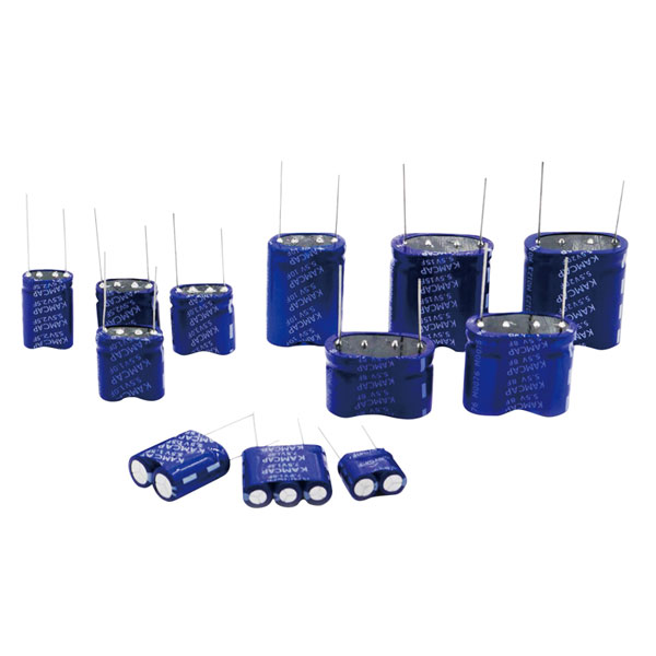
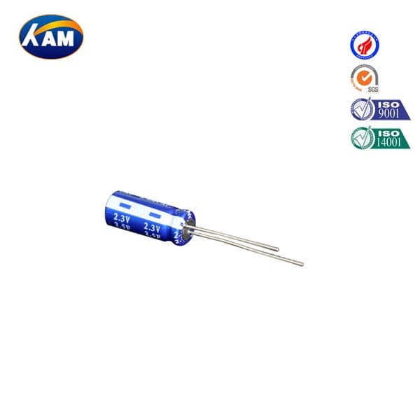
Series-parallel arrangements are common when one string provides enough voltage but not enough energy. Parallel branches should use matched cells and symmetrical connections. For low-voltage equipment, Kamcap combined supercapacitors in series provide preconfigured multi-cell options for meters, motor drives, and backup circuits.
Start with the load. Define the required power, operating time, maximum bank voltage, and the minimum voltage at which the converter or load can continue working.
Usable energy between two voltages is:
Eusable = 1/2 × Cbank × (Vmax² − Vmin²)
The result is in joules. Divide the result by 3,600 to convert it to watt-hours.
Required capacitance can be estimated as:
Crequired = 2 × Erequired / (Vmax² − Vmin²)
Add margin for losses, tolerance, ageing, and temperature.
Consider eighteen identical 3.0 V, 500 F cells connected in series. The theoretical bank voltage is 54 V, while the equivalent capacitance is:
500 F / 18 = 27.8 F
If the system uses the bank from 48 V down to 30 V, the ideal usable energy is approximately:
0.5 × 27.8 × (48² − 30²) = 19,500 J
This is equivalent to approximately:
19,500 / 3,600 = 5.4 Wh
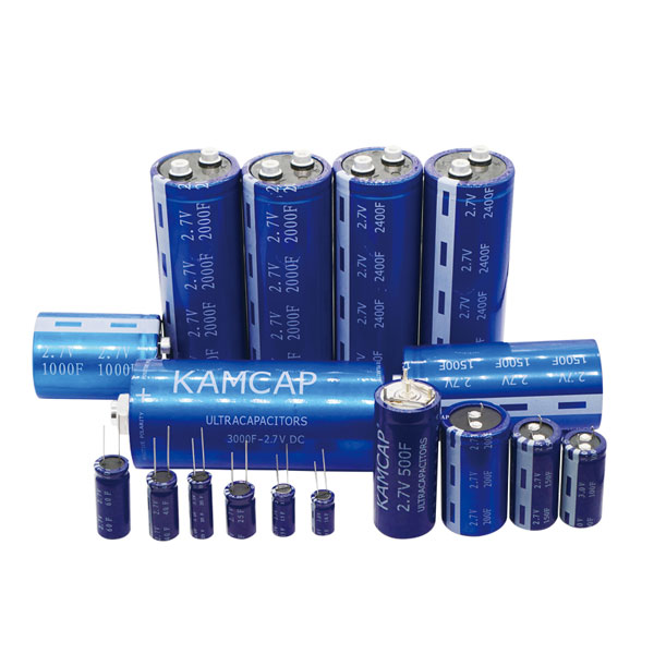
Two identical parallel strings would provide approximately 55.6 F and 10.8 Wh. This type of configuration suits short, high-power events better than long-duration energy supply. Kamcap’s winding series includes 3V supercapacitor options covering a capacitance range from 1 F to 500 F. Using a higher-voltage cell can also reduce the number of cells required in series, depending on the application.
In an ideal string, voltage divides evenly between identical cells. Real cells differ in capacitance, leakage current, ESR, temperature, and ageing rate. These differences can cause one supercapacitor in series to exceed its permitted voltage even when the total bank voltage appears correct. Supercapacitor balancing is therefore necessary for maintaining safe cell voltages and consistent long-term performance.
Two balancing approaches are commonly used.
Passive balancing: Equal-value resistors are installed across the cells. The circuit is simple and inexpensive, but it creates continuous standby loss.
Active balancing: Shunt devices, comparators, MOSFET circuits, or balancing controllers remove or transfer charge when one cell voltage rises above the others. Active control reduces steady-state loss but adds circuit complexity.
Analog Devices identifies equal resistors across each cell as the simplest and most cost-effective voltage-balancing method. It also describes active approaches for systems where continuous resistor losses are undesirable.
For passive balancing, resistor value can be estimated using:
Rbalance = Vcell / Ibalance
Resistor power dissipation is:
Pbalance = Vcell² / Rbalance
The balancing current should be selected according to the cell leakage specification, expected leakage mismatch, and acceptable standby power consumption. Balancing does not replace monitoring. Larger banks should measure individual cell or cell-group voltage, bank current, and temperature. The charger should reduce or stop charging when any monitored value exceeds its defined limit.
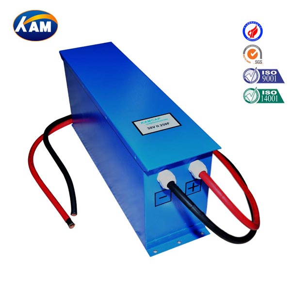
Kamcap’s MK supercapacitor modules cover system voltages from 3.3 V to 120 V and incorporate protection and balancing features for industrial, automotive, and backup-power systems.
Capacitance alone does not show whether an ultra capacitor bank can support the required load. Equivalent series resistance creates an immediate voltage drop when the discharge current changes:
ΔVESR = I × ESRbank
ESR also produces heat:
Pheat ≈ Irms² × ESRbank
For example, a bank with an ESR of 20 mΩ would experience an immediate 2 V voltage drop at a discharge current of 100 A, before accounting for additional resistance from busbars, terminals, fuses, and cables.
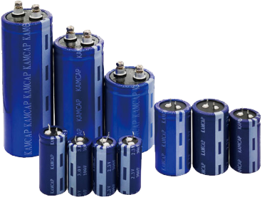
A high-current design may require lower-ESR cells, parallel strings, or larger busbars. All connection resistance should be included in the total resistance budget. Kamcap full-welding supercapacitor cells are intended for large-capacitance, low-resistance applications where robust connections and high-current handling are important.
A production-ready bank should normally include:
Current-limited charging or a controlled pre-charge circuit
Individual cell or cell-group overvoltage detection
Bank overcurrent and short-circuit protection
Temperature monitoring
Reverse-current protection where required
A controlled discharge or service bleed path
Appropriate fuses, contactors, and disconnect devices
Insulated terminals and a safe maintenance procedure
The bank enclosure should provide mechanical support for the cells and busbars. Designers should also consider vibration, thermal expansion, condensation, airflow, and access for inspection. IEC 62391-1:2022, Fixed Electric Double-Layer Capacitors applies to fixed electric double-layer capacitors used mainly in DC electrical and electronic circuits. It provides generic terminology, inspection requirements, and test methods that can support a component qualification plan.
Validation should cover maximum charge voltage, minimum and maximum temperature, peak discharge current, repeated cycling, charger faults, failed balancing components, and long-term float conditions. Individual cell voltages should be recorded instead of relying only on the total bank voltage.
| Design Requirement | Suggested Configuration | Kamcap Product Direction | Main Checks |
|---|---|---|---|
| Compact 5.5–7.5 V backup | Factory-combined series unit | Combined Type Series | Leakage current, backup time, load current, and PCB space |
| Custom bank using 3 V cells | Series or series-parallel cells | 3V Winding Type Series | Cell count, balance circuit, capacitance tolerance, and temperature |
| High-current custom bank | Large cells with low-resistance busbars | Full Welding Series | ESR, pulse current, joint resistance, and fuse rating |
| Industrial 12–120 V system | Protected, pre-engineered module | MK Module Series | Rated voltage, protection interface, mounting, and discharge safety |
Final selection should consider usable energy, peak current, minimum voltage, recharge time, temperature, and service life. Kamcap can support individual cell, combined-unit, and supercapacitor module selection for OEM projects. However, the completed bank should still be verified with the actual charger, converter, enclosure, wiring, and load profile used in the final equipment.
A super capacitor bank has a voltage that falls continuously during discharge and is normally suited to rapid charging, pulse power, and frequent cycling. A battery bank generally maintains a flatter discharge voltage and provides longer runtime.
Divide the highest expected system voltage by the permitted working voltage per cell and round the result up. Additional voltage margin should be included for charger tolerance, voltage imbalance, temperature, and transient conditions.
The voltage capability increases, while equivalent capacitance decreases. With identical cells, Ns cells provide approximately Ns × Vcell voltage and Ccell / Ns capacitance. Their individual ESR values also add together.
Yes. Parallel connection increases total capacitance and can reduce equivalent ESR. Cells or complete strings should be matched and connected symmetrically to support even current sharing.
A balancing strategy is generally needed because leakage current and capacitance vary between cells. The choice between passive and active balancing depends on standby-loss limits, cell count, charge rate, and required voltage accuracy.
Individual cells provide more configuration flexibility but require custom balancing, protection, interconnections, and mechanical support. Pre-engineered supercapacitor modules are often more practical when their voltage, capacitance, protection, and mounting format match the equipment.
Kamcap specializes in the development, production, and sales of supercapacitors. If you are interested, please contact us by phone +86-18640666860 or email info@kamcap.com.


 English